Solder —
” 1. Any of various fusible alloys, usually tin and lead, used to join metallic parts.
You simply need to place your soldering iron onto the contact to melt the solder.
When the solder in the contact melts, slide the wire into the contact.
Remove the iron and hold the wire still while the solder solidifies again.
You will see the solder ‘set’ as it goes hard.
Solder should all take around 1-3 seconds.
A good solder joint will be smooth and shiny.
If the joint is dull and crinkly, the wire probably moved during soldering.
If you have taken too long it will have have solder spikes.
If it does not go so well, you may find the insulation has melted, or there is too much stripped wire showing. If this is the case, you should desolder the joint and start again.
==========================================================================
Flux —
” a substance used to promote fusion (as of metals or minerals); especially : one (as rosin) applied to surfaces to be joined by soldering, brazing, or welding to clean and free them from oxide and promote their union.” (merriam webster dictionary).
==========================================================================
Relays —
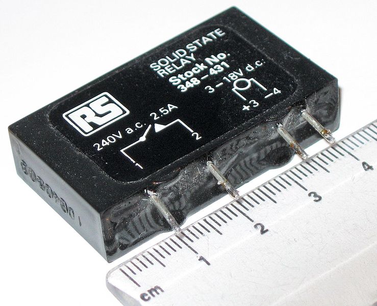
“A relay is an electrically operated switch. Many relays use an electromagnet to operate a switching mechanism mechanically, but other operating principles are also used. Relays are used where it is necessary to control a circuit by a low-power signal (with complete electrical isolation between control and controlled circuits), or where several circuits must be controlled by one signal. The first relays were used in long distance telegraph circuits, repeating the signal coming in from one circuit and re-transmitting it to another. Relays were used extensively in telephone exchanges and early computers to perform logical operations.
A type of relay that can handle the high power required to directly control an electric motor is called a contactor. Solid-state relays control power circuits with no moving parts, instead using a semiconductor device to perform switching. Relays with calibrated operating characteristics and sometimes multiple operating coils are used to protect electrical circuits from overload or faults; in modern electric power systems these functions are performed by digital instruments still called “protective relays”.” (From Wikipedia).
Transitors — pay attention to the flat side
A Transistor is an semiconductor which is a fundamental component in almost all electronic devices. Transistors are often said to be the most significant invention of the 20th Century. Transistors have many uses including switching, voltage/current regulation, and amplification – all of which are useful in renewable energy applications.
A transistor controls a large electrical output signal with changes to a small input signal. This is analogous to the small amount of effort required to open a tap (faucet) to release a large flow of water. Since a large amount of current can be controlled by a small amount of current, a transistor acts as an amplifier.
A transistor acts as a switch which can open and close many times per second.
A bipolar junction transistor has three terminals – Base, Collector, and Emitter corresponding to the three semi-conductor layers of the transistor. The weak input current is applied to the inner (base) layer. When there is a small change in the current or voltage at the inner semiconductor layer (base), a rapid and far larger change in current takes place throughout the whole transistor.
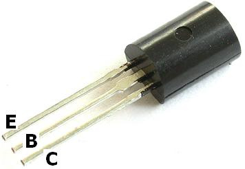
Pictured below is a schematic diagram of the more common NPN transistor.

==========================================================================
Resistor —
Resistors restrict the flow of electric current, for example a resistor is placed in series with a light-emitting diode (LED) to limit the current passing through the LED.
Picture below: OHM Resistor

Make sure the color matches up to the resistor you want to use…
Most resistors have 4 bands:
- The first band gives the first digit.
- The second band gives the second digit.
- The third band indicates the number of zeros.
- The fourth band is used to shows the tolerance (precision) of the resistor, this may be ignored for almost all circuits
You can follow this link for some help…
==========================================================================
Timmer Resitor—
is a highly stable controller capable of producing accurate time delays or oscillation. In the time delay mode of operation, the time is precisely controlled by one external resistor and capacitor. For a stable operation as an oscillator, the free running frequency and the duty cycle are both accurately controlled with two external resistors and one capacitor.
The circuit may be triggered and reset on falling waveforms, and the output structure can source or sink up to 200mA.
==========================================================================
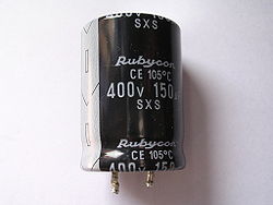
Capacitors — ” Capacitors are widely used in electronic circuits for blocking direct current while allowing alternating current to pass, in filter networks, for smoothing the output of power supplies, in the resonant circuits that tune radios to particular frequencies and for many other purposes. ” — Wikipedia
IC Sockets — (IC socket) A CPU socket or CPU slot is an electrical component that attaches to a printed circuit board (PCB) and is designed to house a microprocessor. It is a special type of integrated circuit socket designed for very high pin counts.
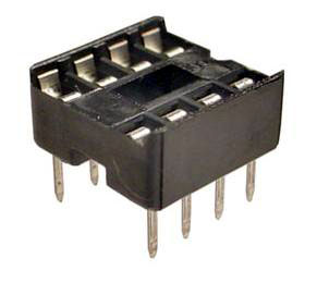
A CPU socket is made of plastic, a metal lever or latch, and metal contacts for each of the pins or lands on the CPU. Many packages are keyed to ensure the proper insertion of the CPU. CPUs with a PGA package are inserted into the socket and the latch is closed.
==========================================================================
Timer Integrated Circuit or IC —
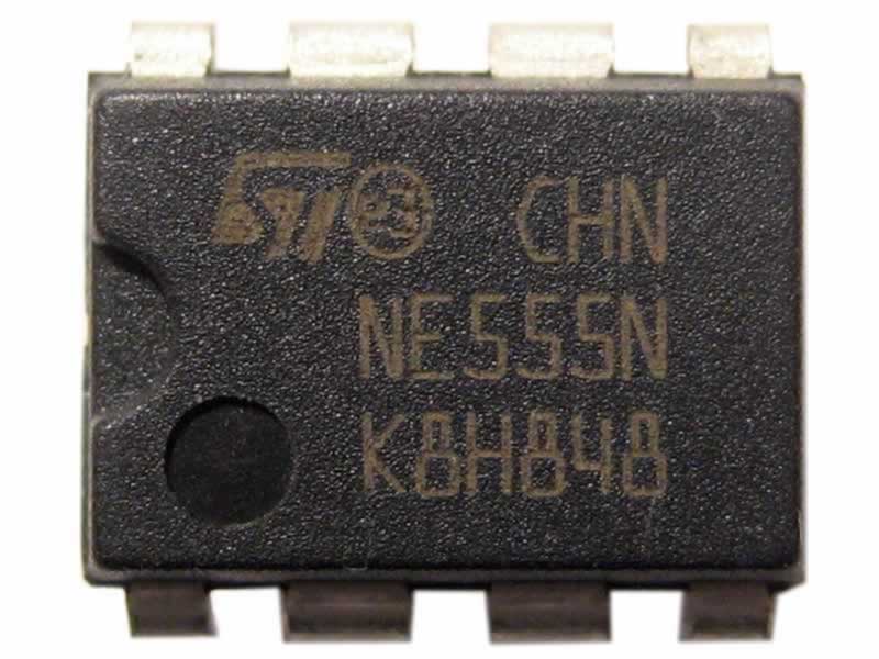
“The 555 timer IC is an integrated circuit (chip) used in a variety of timer, pulse generation and oscillator applications. The part is still in widespread use, thanks to its ease of use, low price and good stability. As of 2003, it is estimated that 1 billion units are manufactured every year.” — Wikipedia
==========================================================================
Light Emitting Diode or LED —
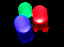
A light-emitting diode (LED) is a semiconductor light source.[1] LEDs are used as indicator lamps in many devices and are increasingly used for other lighting. Introduced as a practical electronic component in 1962,[2] early LEDs emitted low-intensity red light, but modern versions are available across the visible, ultraviolet and infrared wavelengths, with very high brightness.
=======================================================================
Potentiometer —

A potentiometer , informally, a pot, is a three-terminal resistor with a sliding contact that forms an adjustable voltage divider. If only two terminals are used (one side and the wiper), it acts as a variable resistor or rheostat. Potentiometers are commonly used to control electrical devices such as volume controls on audio equipment. Potentiometers operated by a mechanism can be used as position transducers, for example, in a joystick.
Potentiometers are rarely used to directly control significant power (more than a watt), since the power dissipated in the potentiometer would be comparable to the power in the controlled load (see infinite switch). Instead they are used to adjust the level of analog signals (e.g. volume controls on audio equipment), and as control inputs for electronic circuits. For example, a light dimmer uses a potentiometer to control the switching of a TRIAC and so indirectly control the brightness of lamps.